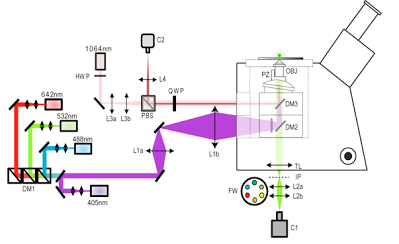
Components of our single-molecule localization microscope
Four lasers with excitation wavelengths of 405nm, 488nm, 532nm and 642nm were expanded to a beam diameter of 2mm and combined into a single co-linear beam using dichroic mirrors (DM1). Two achromatic lenses (L1a & b) were used to expand the excitation beam and to obtain a homogeneous illumination over fields of view as large as 40x40µm². The lasers were focused by L1b, located near the back port of the microscope, and directed by dichroic mirror DM2 to the back focal plane of a 100x Plan-Apo oil objective (OBJ, NA = 1.4) mounted on a z-direction piezoelectric stage (PZ). L1b can be translated perpendicularly to the optical axis in order to shift between TIRF and epifluorescence imaging mode, depending on the experiment. A motorized stage is used to translate the sample perpendicularly to the optical axis.
Fluorescence from the sample is collected by the objective, separated from laser light by dichroic mirrors DM2 and DM3 and focused by the tube lens (TL) on the microscope original imaging plane (IP). A pair of achromatic relay lenses arranged as a telescope (L2a & b) is used to form an image on the EMCCD camera sensor (C1) while increasing the total magnification of the system (effective pixel size of 115nm). A motorized filters wheel (FW) placed between the two lenses allows for the selection of the fluorescence emission filter.
Control software for the lasers and the filter wheel was written in LabView 2010 (National Instrument, France). The emission intensity of each laser is controlled individually using a USB-DAQ device (National Instruments). Specific electronic circuits were designed for the control of the 532nm and the 561 lasers.
To avoid loss of focus during PALM acquisition, an active autofocus system was built. In a separate path from the other four lasers, a linearly polarized 1064nm IR beam from an Ytterbium fiber laser is expanded twice (L3a & b) and passes through an optical separator formed by a polarized beam splitter (PBS) and a quarter wave plate (QWP). The beam is directed towards the objective lens by dichroic mirror DM3. Depending on the sample and the position of the plane imaged by the objective, the distance between L3a and L3b can be modified to ensure that the IR beam is always focused at the glass/sample interface. Part of the IR beam is reflected by the sample, collected by the objective and redirected towards the PBS following the same path than the incident beam. Due to a change in polarization introduced by reflection at right angles, the reflected beam is redirected by the PBS towards lens L4 and imaged on a CCD detector (C2). A half-wave plate (HWP) is used to manually adjust the intensity of the incident beam.
Control software for the autofocus was written in LabView 2009, using the PID and Fuzzy Logic Toolkit. A feedback loop between the CCD detector (C2) and the piezo stage (PZ) makes sure that the sample remains in focus at all times during the PALM acquisition (resolution of ~5-10 nm over hours). At the beginning of each experiment, a calibration is carried out to ensure that the intensity of the IR reflection varies linearly over a course of 600nm around the plane imaged by the objective. When the acquisition starts, the intensity of the IR reflection is used as reference and axial drift is corrected by adjusting the position of the objective.
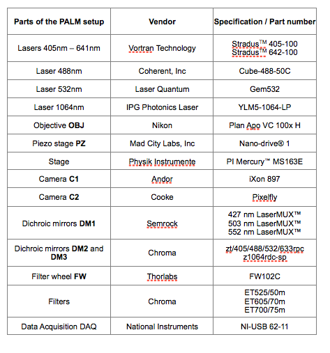
Components

